Tel: +86-18929108896 Email: solomon@sum-ho.com
- All
- Product Name
- Product Keyword
- Product Model
- Product Summary
- Product Description
- Multi Field Search


Views: 0 Author: Site Editor Publish Time: 2026-08-09 Origin: Site


Accurate measurement of automotive control cable travel is the dividing line between precise mechanical actuation and catastrophic system failure. A tiny miscalculation often leaves critical components binding or failing to engage entirely. Engineers frequently over-index on "overall length" while miscalculating the actual stroke. This oversight leads directly to parts bottoming out, snapping under sudden tension, or suffering from unpredictable "lost motion." Relying exclusively on total wire dimensions ignores the dynamic shifting between the inner core and outer conduit. Moving from a broken prototype to a scalable production run requires standardizing how you measure travel length. You must deliberately account for routing geometry, friction, and inherent slack. You also need to partner with an assembly manufacturer testing rigorously for specific tolerances. We will explore standard measurement techniques, compensation methods for bend radii, and the distinct impact of terminal fittings. You will learn how to secure perfect actuation for any vehicular application.
Defining the core terminology prevents expensive engineering mistakes. Overall Length (OAL) measures the entire assembly from the extreme left tip to the extreme right tip. It includes both the outer casing and the inner core. Travel, or stroke, measures something entirely different. Travel is exclusively the movement of the inner wire extending from the outer casing. It represents the exact physical distance the inner core travels from a fully retracted position to a fully extended position. You must separate these two concepts completely when drafting specifications.
The anatomy of travel relies on the relationship between fixed and moving parts. The outer conduit remains stationary. It mounts to the chassis or bulkhead. The inner core slides back and forth inside this conduit. This sliding action transfers force from an input point, like a pedal, to an output mechanism, like a throttle body. If you misjudge this sliding distance, the mechanism cannot operate across its full required range.
Relying solely on OAL introduces severe business risks. Ordering parts based entirely on OAL without specifying exact travel guarantees fitment issues during installation. A procurement team might receive an assembly matching the chassis routing perfectly. However, the inner core might lack the required extension to engage a transmission gear. This specific error drives up revision costs immediately. It delays production schedules while engineers redesign the internal geometry. Specifying precise automotive control cable travel parameters prevents these exact failures. Accurate stroke documentation ensures the component performs flawlessly right out of the box.
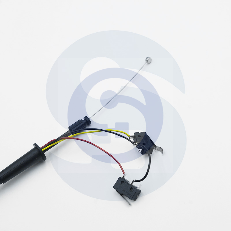
You need a standardized approach to capture usable stroke accurately. Measuring a loose component on a workbench often yields false data. The push-pull measurement technique eliminates this variance. It isolates the inner core movement from casing flex.
Follow this precise push-pull technique to establish your baseline:
Your end fittings determine your ultimate measurement methodology. You must choose between "hole-to-hole" and "tip-to-tip" tracking. Use the hole-to-hole method when dealing with clevis ends or eyelet fittings. You measure directly from the center of the first mounting hole to the center of the opposite mounting hole. This accounts for the pivot point of the mechanism. Conversely, use the tip-to-tip method for bare wire configurations or threaded rod ends. You measure from the absolute end of the hardware. Mixing these two methods creates instant length discrepancies.
Establishing the correct "mid-stroke" baseline ensures proper dual-directional functionality. Identifying the exact center of the travel proves critical for equal actuation in push-pull linkages. Gear shifts and complex throttle bodies depend on symmetrical movement. If you offset the baseline, the linkage will over-extend in one direction and under-extend in the opposite direction. Finding the true mechanical center prevents grinding gears and erratic throttle responses.
Raw bench measurements never equal real-world performance. You must account for lost motion. Lost motion defines the physical gap or clearance between the inner cable and the outer conduit. Manufacturers design this clearance intentionally. It allows the inner core to slide without binding. However, this necessary gap creates inherent backlash. Before the force reaches the end mechanism, the inner core shifts laterally inside the conduit to absorb this slack.
Routing complex paths introduces a severe bend radius penalty. Routing the assembly through a cramped vehicle chassis always introduces friction. Tight bends force the inner wire to scrape along the outer radius of the conduit wall. This action takes up internal slack prematurely. It effectively reduces the functional travel length at the endpoint. A component measuring 50 millimeters of stroke on a straight workbench might only deliver 46 millimeters once installed around a 180-degree firewall bend.
You must calculate a buffer to compensate for these physical realities. Applying a percentage-based or static measurement buffer to your theoretical travel length neutralizes routing inefficiencies. Engineers analyze the total degrees of bend in the installation path. They then add supplementary travel to the initial specification. This buffer guarantees the end mechanism receives the full required force despite internal friction.
| Routing Complexity | Total Degree of Bends | Estimated Lost Motion Buffer Addition |
|---|---|---|
| Straight Path (Minimal Friction) | Under 90° | Add 1-2% of total theoretical travel |
| Moderate Routing (Chassis curves) | 90° to 180° | Add 3-5% of total theoretical travel |
| Complex Routing (Multiple switchbacks) | Over 180° | Add 6-10% of total theoretical travel |
Best Practice: Always physically mock up your routing path using flexible tubing before finalizing your buffer percentage. Simulated bends often miss pinch points found in the actual chassis.
Hardware selection dictates your margin for error. End fittings anchor the assembly to the vehicle. Their specific design directly influences how strictly you must control your travel measurements.
Analyzing fixed versus adjustable fittings reveals distinct engineering trade-offs.
You must also anticipate the impact of fitting compression. The manufacturing process itself alters dimensions. Crimping or swaging presses metal dies onto the wire and casing. This extreme pressure physically deforms the materials. It can marginally alter the final travel length if the manufacturer lacks precision tooling. A heavy-handed crimp can stretch the inner wire slightly. A loose crimp can compress the outer casing. Both scenarios ruin your carefully calculated baseline. You must demand strict tooling calibration from your supply partners to prevent compression discrepancies.
Shifting from technical specifications to actual sourcing demands a rigorous evaluation process. You must translate your travel measurements, routing buffers, and fitting requirements into an actionable Request for Quote (RFQ). Handing a basic napkin sketch to a mass-production facility guarantees failure. You need a specialized manufacturer capable of digesting complex actuation data.
Evaluate your potential suppliers across three critical dimensions. First, scrutinize their application engineering capabilities. Do they blindly build to your print? A top-tier partner audits your travel length parameters before touching a machine. They verify your lost motion calculations and challenge your buffer estimates for actual manufacturability. They flag impossible bend radii immediately.
Second, investigate their in-house testing capabilities. Look for suppliers offering robust physical validation. They should perform in-house tensile testing and proof-loading. They must utilize automated lifecycle cycle-testing. This testing proves the stroke remains completely consistent under maximum load over time. Simulating one million actuations on a test bench exposes wire stretching and casing degradation long before the part reaches a consumer.
Third, demand strict compliance and traceability. Ensure they adhere strictly to automotive quality management standards. Certifications like IATF 16949 or ISO 9001 are mandatory. These frameworks guarantee tolerance consistency across high-volume runs. Statistical process control prevents a batch of ten thousand units from drifting out of spec over a three-month production window.
Apply strict shortlisting logic when finalizing your decision. Rule out suppliers immediately if they cannot articulate how they compensate for casing compression. They must understand how inner wire stretch behaves during the swaging process. If they treat your Automotive Control CableCustom Automotive Cable Assembly as a generic wire rope order, walk away. Precision automotive linkages require dedicated mechanical expertise.
Measuring automotive control cable travel remains a strict, unforgiving engineering exercise. You absolutely must look beyond overall length. Securing precise actuation means accounting deliberately for lost motion, routing curves, and the physical limitations of specific end fittings. Ignoring these variables guarantees mechanical binding, erratic performance, and total system failure in the field.
We advise engineers to standardize their data collection immediately. Document your push-pull stroke data meticulously using fixed anchors. Map out your physical routing restrictions directly on the chassis to identify friction zones. Finally, prepare a comprehensive drawing detailing every tolerance, buffer, and attachment point clearly.
Do not leave your actuation performance to chance. Consult with a specialized custom cable manufacturer to validate your travel measurements today. Submit your detailed RFQ and request a physical prototype. Subject that prototype to aggressive real-world application testing to ensure flawless engagement before launching full-scale production.
A: In automotive engineering, the terms are generally used interchangeably. Both refer to the maximum linear distance the inner cable can extend and retract relative to the fixed outer conduit.
A: Assemble the broken pieces of the inner wire and measure the total core length. Then, measure the exact length of the outer casing. Subtract the casing length from the total core length to find the total exposed wire, which serves as the foundational number for determining the original travel (minus fitting deductions).
A: This is typically caused by "lost motion." Tight bends in the routing path force the inner cable to travel along the outer radius of the casing, eating up the functional stroke before the force reaches the end mechanism. Ensure your custom assembly accounts for this required slack.
